Mechanical Engineering Courses
AUTOCAD - 2D
AutoCAD 2d is primarily used to create 2d drawings. It is used across industries such as mechanical, civil, automobile, etc. You can draft and edit 2d drawings, create isometric views in AutoCAD 2d
2D - DRAWING

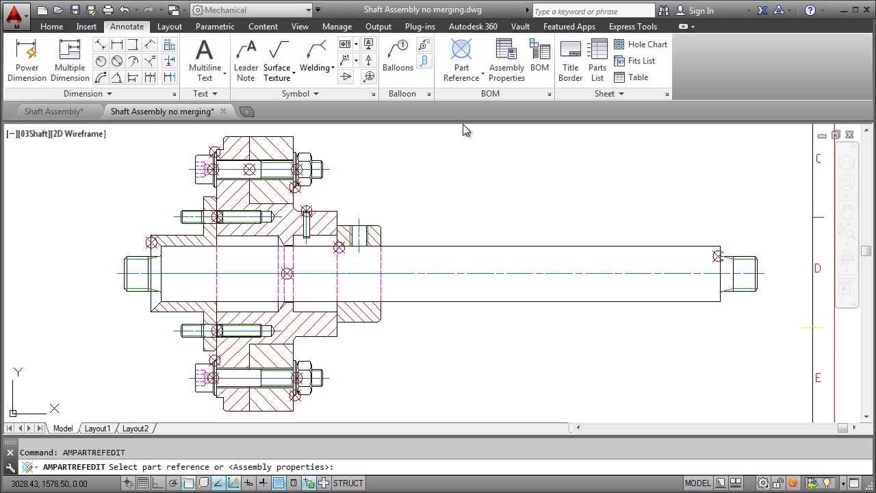
AutoCAD 2D Drawing shows the dimensions and different views of the profile designed.
2D-AUTOCAD PART

Parts are the building blocks of every 2D AutoCAD model. Each assembly and drawing you create is made from parts.
3D-AUTOCAD ASSEMBLY

Assembly objects contain and manage a collection of subassemblies that are used to form the basic structure of a 3D AutoCAD model.
3D-h4 AUTOCAD MODEL
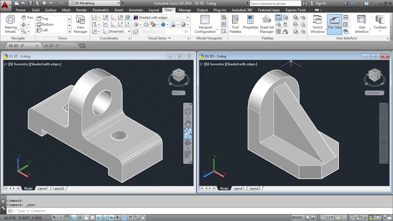
Three-dimensional (3D) models represent a body using a collection of points in 3D space, connected by various geometric entities such as triangles, lines, curved surfaces etc.
CATIA ASSEMBLY

Assembly modelling is a technology and method used in CATIA to handle multiple files that represent components within a product.
CATIA-DRAWING

Front view, Top view, Side view of the designed profile with its dimensions.
CATIA-PART
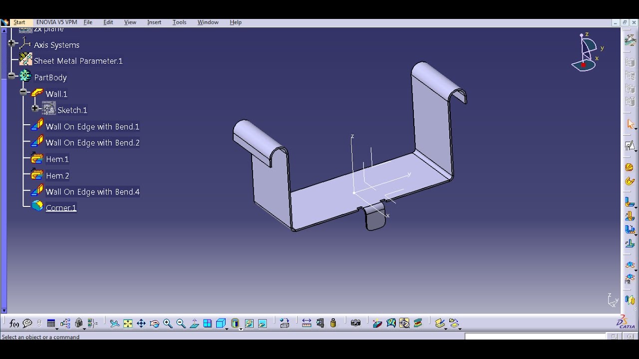
Modelling techniques used to create and edit designs and feature-based solids are explored.
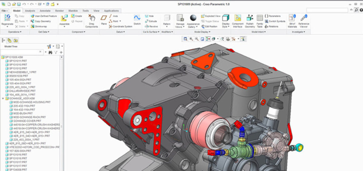
CREO-ASSEMBLY

An assembly describes the procedure of assembling parts created in part mode.
CREO-DRAWING

Drawing let you create and manipulate detailed engineering that use a 3D model as a geometry source.
CREO-PART
In part modeling you can create a part from conceptual sketch through solid-based modeling, as well as build and modify parts
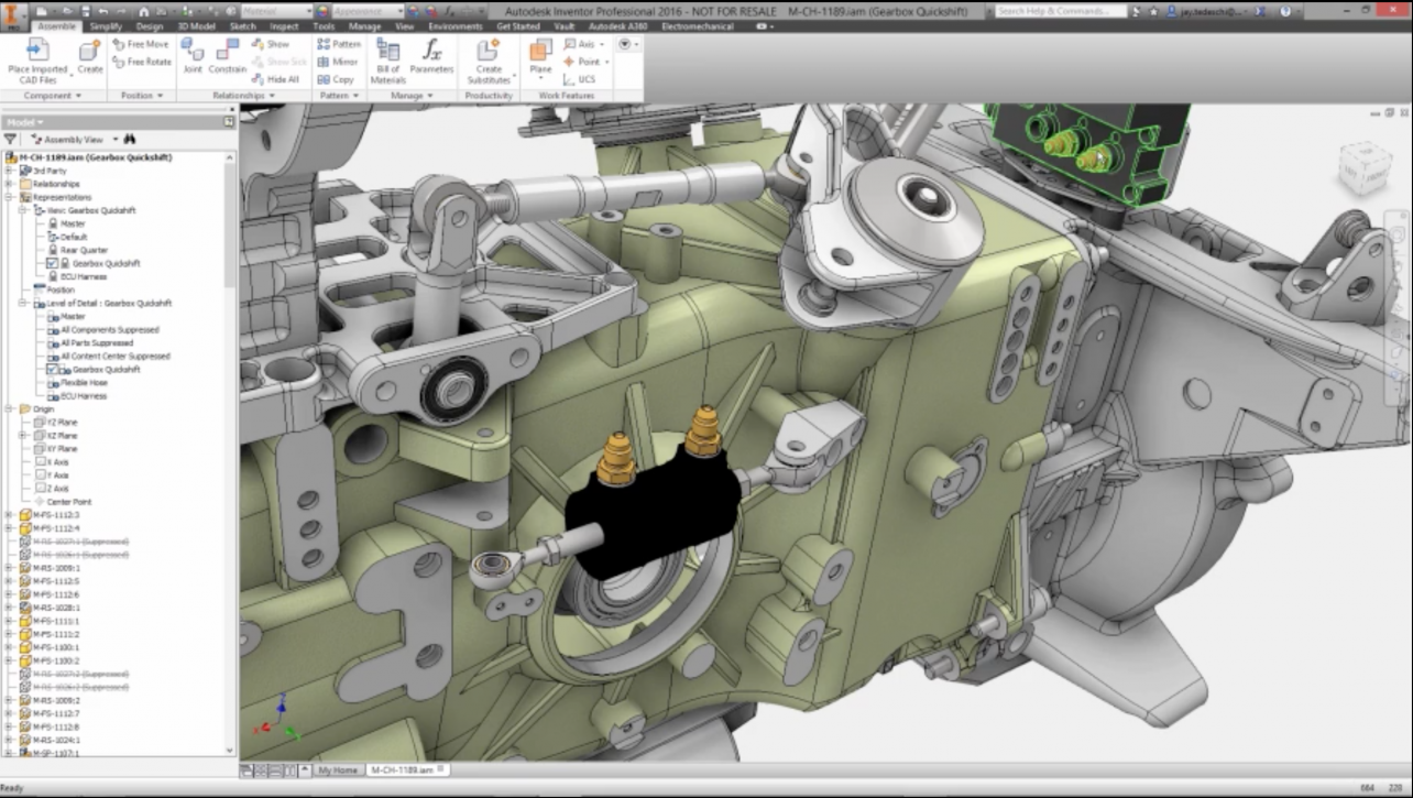
INVENTOR-ASSEMBLY
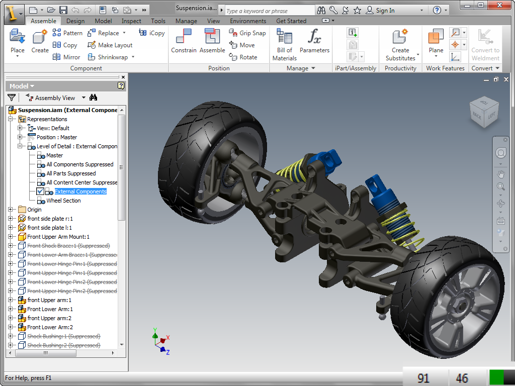
To create an assembly in Inventor, insert components into an assembly or create parts and subassemblies inside an assembly file. Then, use commands to define relationships, position, and DOF.
INVENTOR-DRAWING

Drawing dimensions are added to a drawing to further document the model, without changing or controlling features or part size.
INVENTOR-PART
Select features, bodies, surfaces, visible 2D and 3D sketches, work features, parameters, and iMates to include or exclude from the derived part.
NX-ASSEMBLY

NX assembly arrangement allows the user to configure and show different positions in assembly documentation. This helps in making different views or positions of your model.
NX-DRAWING
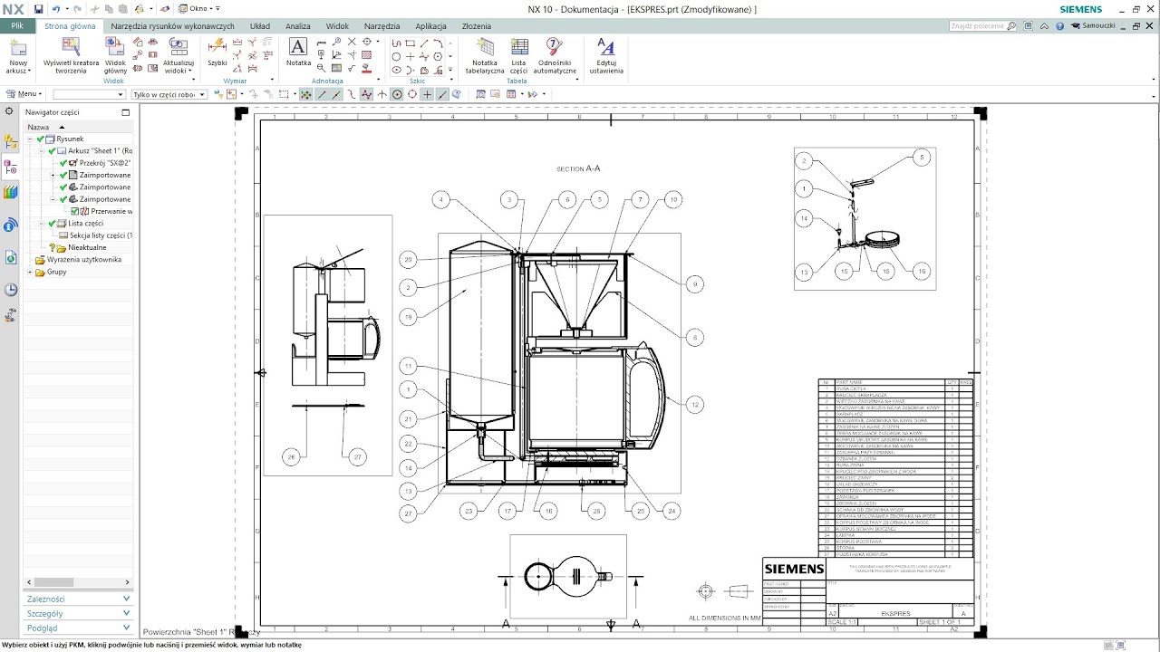
It represent the 2D structure of a 3D object using multiple views such as standard 3 view, section view etc..
NX-PART
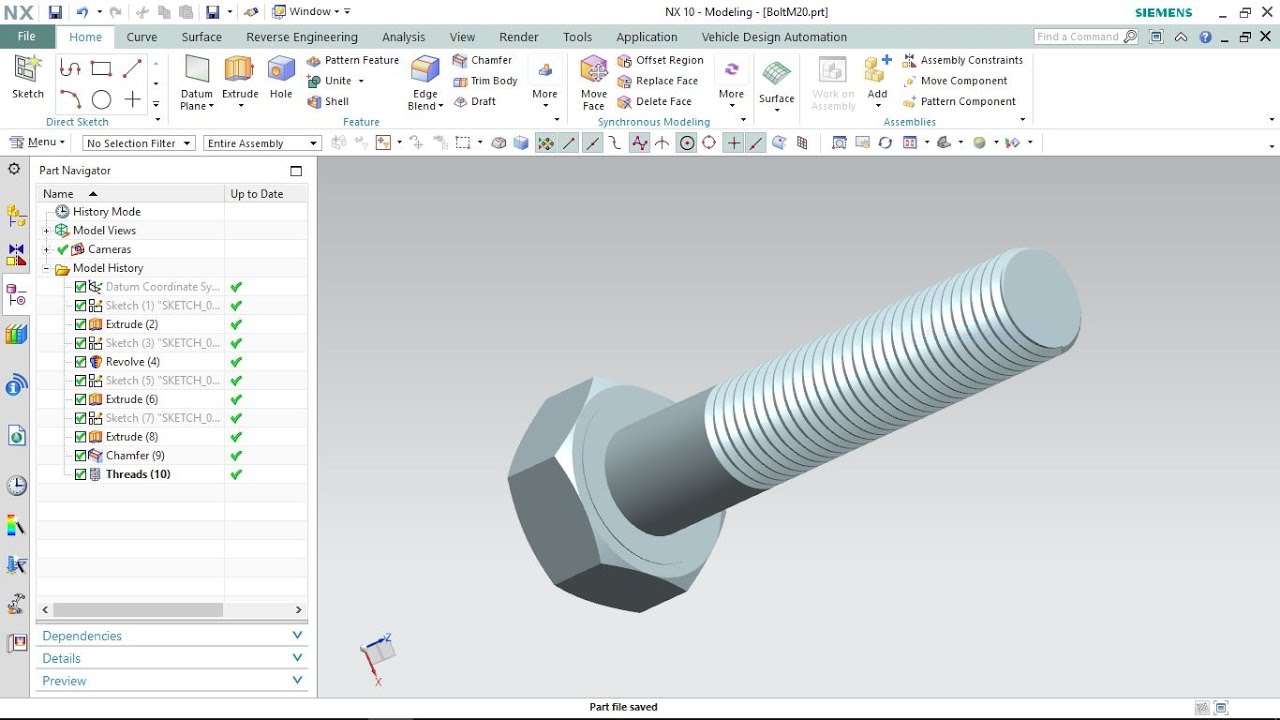
NX combines wireframe, surface, solid, parametric and direct modeling in a single modeling software that allows you to choose the best tool to make part your parts for design.
SOLID-ASSEMBLY
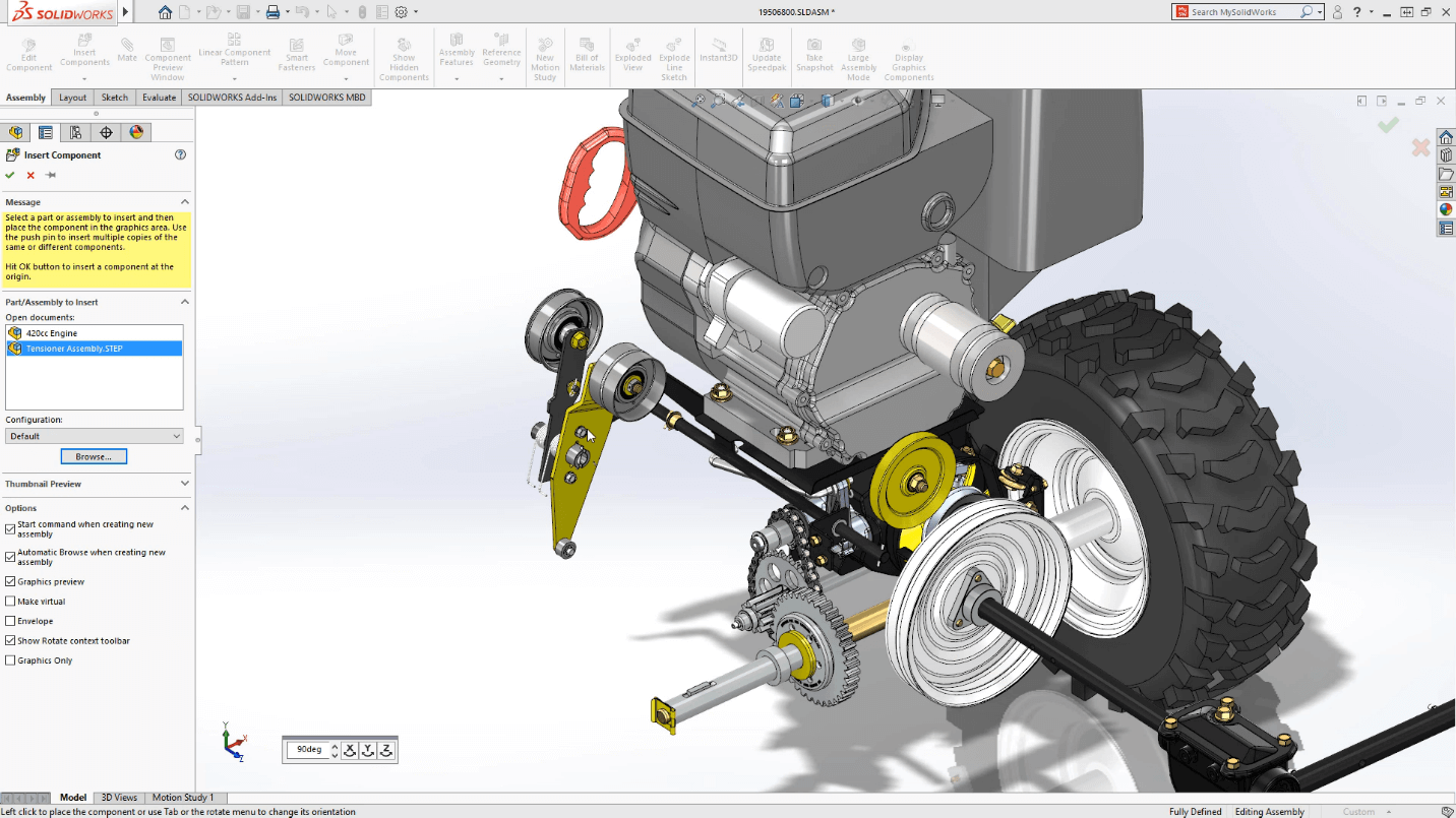
An assembly is a collection of related parts saved in one SolidWorks document file. It also contains other assemblies which are known as subassemblies.
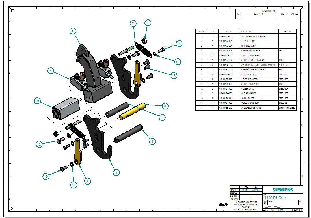
SOLID-DRAWING
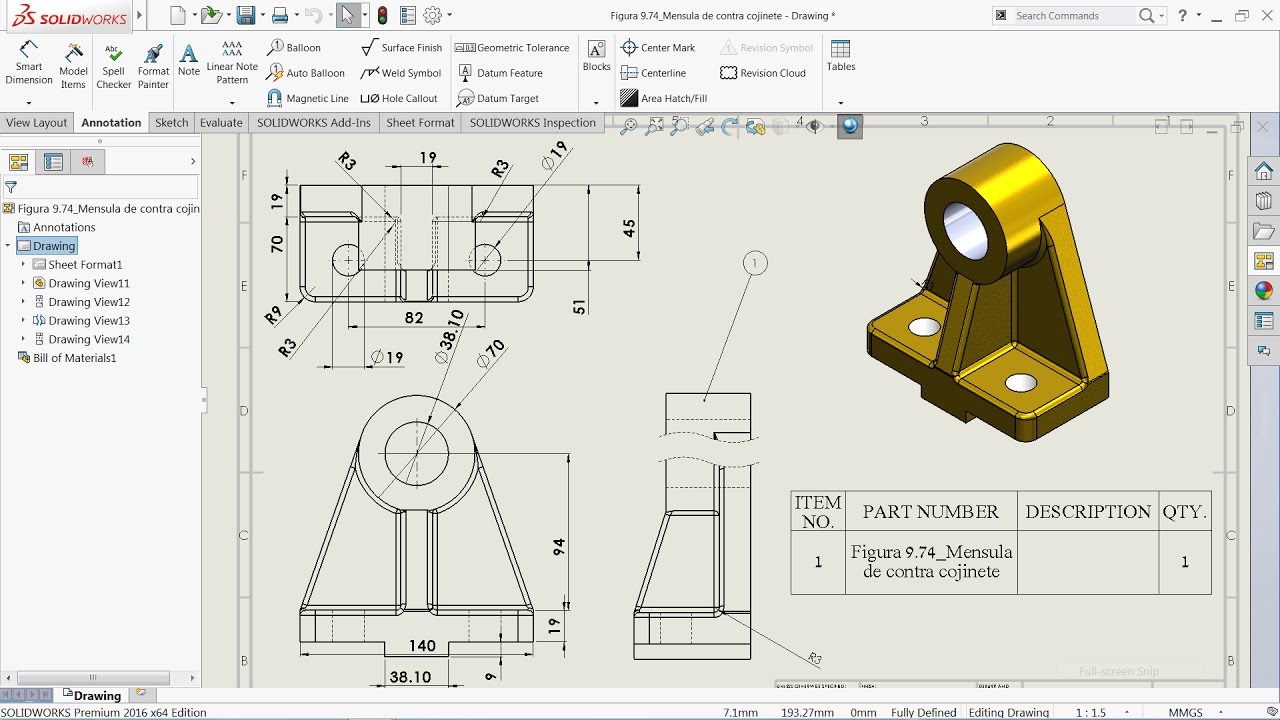
You can create drawings from part or assembly models. Drawings are available in multiple views such as standard 3 views and isometric views (3D). You can import the dimensions from the model documents.
SOLID-PART
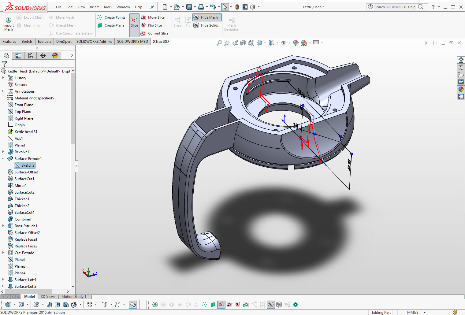
SolidWorks parts are the basic building blocks in SolidWorks software. A part is a 3D geometry that defines its edges, faces and surfaces.
SOLIDEDGE-DRAWING
Drawing production is the process of formally documenting the design of a part or assembly.
SOLIDEDGE-PART
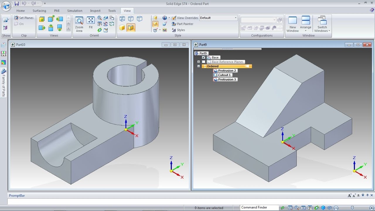
A part is the fundamental element before making the assemblies of a product.
SOLIDEDGE-ASSEMBLY
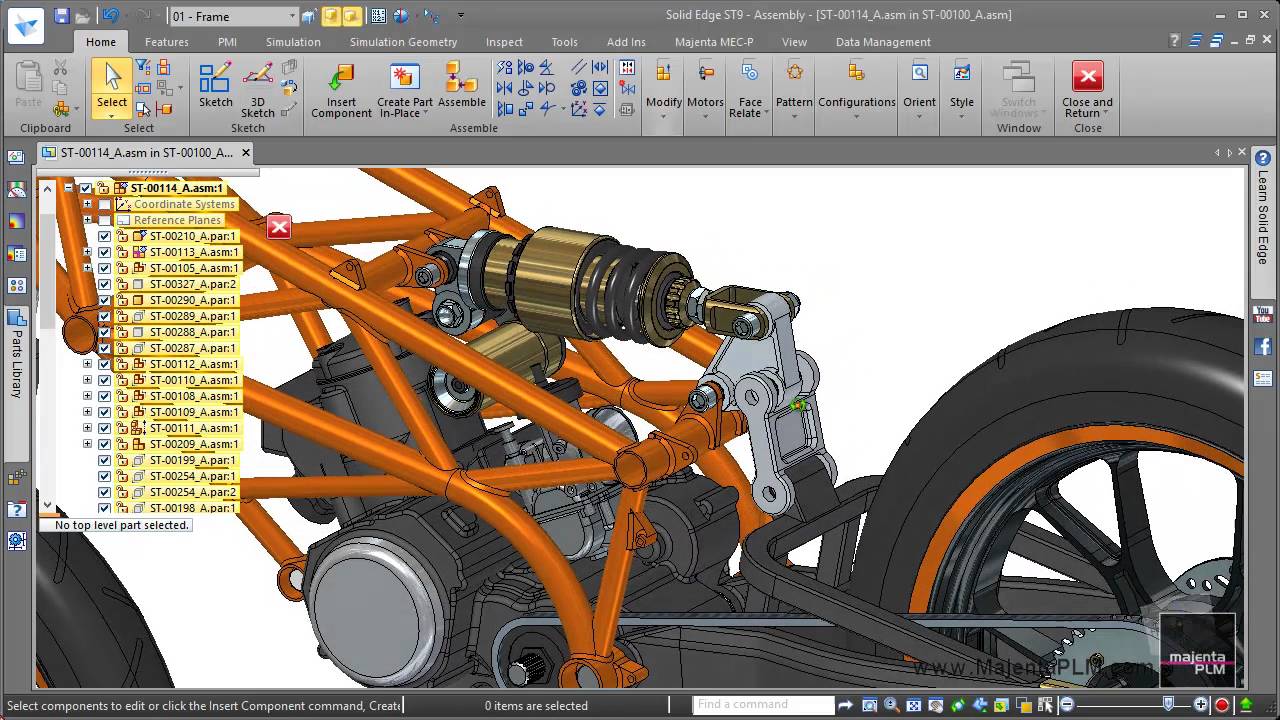
An assembly is a collection of parts and subassemblies that are positioned in a meaningful way. SolidEdge assembly provides the tool needed to lay out and position the parts relative to each other.
SWANSOFT-LATHE

Swan soft CNC Simulator is real time 3D CNC machine system simulation and advanced G-code verification software. It allows the user to simulate all the CNC machine operations and debug NC code using the same platform.
AUTOCAD-2D
- How to install AUTOCAD
- Introduction to Engineering Drawings
- Projections (First & Third angle), Views (Orthographic, Isometric @ Perspective)
- Introduction to AutoCAD
- History, Workspaces, Co-ordinate system
- Drawing settings
- Units, Limits
- Drafting settings
- Ortho, Polar, Grid , SnapPolar tracking, Selection Cycling
- Object snap, Dynamic inputs, Quick properties
- Drawing tools
- Line, Circle, Arc, Ellipse, Donut, Polygon, Rectangle, Point, Spline, Xline, Trim, Extend, Break, Erase, Undo, Redo, Explode, Modify Tools,
- Measure, Point Style,Ray, Wipeout, Revision,Join, Chamfer,Lengthen,
- Move, Copy, Rotate , Mirror, Array, Align, Scale, Stretch,Cloud, Multiline, Pline, Fillet, Divide,
- Display control
- Limits, Zoom, PAN, Redraw, Clean Screen, Steering Wheels,Regen
- Object Properties
- Color, Line type, Lt scale , Line weight
- Match Properties, Transparency, List
- Annotation Tools
- Dimension, Linear, Aligned, Radius, Diameter, Center,
- Arc length, Continuous ,Mark , Angle, Baseline Tolerance
- Dimension Space, Dimension Break, Jogged radius, Dimension Edit
- Ordinate dimensions, Centre Mark, Centre line, Dimension Style,
- Annotation Tool
- Leader, Qleader, Mleader, Mleader style, Table edit,Spell, Table, Table style,
- Add leader, Align Leader lines, Collect Leader, Mtext, Scale text, Text, Style,
- Hatching Objects
- Hatch Gradient, Hatch edit
- Parametric Modeling
- Geometric Constraint, Dimensional Constraint
- Design Centre, Tool Palette
- Isometric View Drawings
- Clipboard
- Copy, Copy base, Copy link , Paste clip Paste special, Paste block, Paste original
AUTOCAD 3D
- Topics
- Need of 3rd dimension, The conventions of AutoCAD
- Co-ordinate systems in 3D Types of 3D Models
- Orthographic Views
- Create
- Box, Extrude,
- Revolve, Loft , Sweep
- Editing tool
- Press pull, Union, Subtract, Intersect
- Drawing tool
- Line, Polygon
- Modifying tool
- Move , Offset, Copy, Erase
- 3D Mirror, Fillet, Chamfer
- Selection
- Culling, No Filter, Move Gizmo
- Coordinates
- World, X, 3 Points
- Mesh
- Smooth Object, Smooth More,
- Smooth less , Smooth Refine
- Solid Editing
- Solid Union, Interference Checking,
- Extract Edges, Solid Subtract
- Slice, Extrude Faces,
- Solid Intersect , Thicken, Separate
- Section Plane
- UCS
- UCSICON, DDUCSP, UC
- UCSMAN, UCSFOLLOW
- Rotate3D, Mirror3D, 3DArray
- 3D View
- PLAN, 3DORBIT, 3DDISTANCE, 3DSWIVEL
- 3DCLIP, 3DCORBIT, SHADEMODE, Render
- Solid model Display
- ISOLINESDISPSILH,
- FACETRES, SECTION, SLICE
- SOLVIEW, SOLDRAW, AMECONVERT, ACISIN
- SOLPROF, MASSPROP, ACISOUT,
- EXPORT, IMPORT, STLOUT
- Advanced layouts
- Quick View Layouts ,
- Creating and Using Named Views
- Advanced Viewport Options,
- Layer Overrides in Viewports
- Additional Annotative Scale Features
Solid Work
- Introduction to SolidWorks
- Features of SolidWorks
- Sketch Entities
- Center line, Line , Circle , Arc, Ellipse, Rectangle,
- Slots, Polygon, Parabola, Ellipse, Partial Ellipse
- Spline , Spline tools, Spline on surface, Equation driven curve
- Construction Geometry , Snap, Grid, Points, Text
- Sketch Tools
- Fillet, Chamfer, Offset, Convert Entities, Intersection curve
- Face curve, Trim , Extend, Split, Jog line,Scale, Stretch
- Mirror , Dynamic Mirror, Move, Copy , Rotate
- Part Modeling
- Extrude, Revolve, Swept , Loft, Boundary Boss/Base
- Extrude cut, Hole wizard, Revolved cut, Swept cut
- Lofted cut, Boundary cut, Fillet, Chamfer
- Linear pattern, Circular pattern , Mirror
- Rib , Draft, Shell, Wrap , Intersect
- Reference Geometry
- Points, Axis, Coordinate System
- Curves
- Split line, Project curve, Composite curve
- Curve through points,
- Helix and Spiral
- Advanced Modeling tools
- Dome, Free Form, Shape feature, Deform, Indent, Flex
- Assembly Modeling
- Introduction- Top down and Bottom up approach
- Standard Mates,
- Coincident,
- Parallel, Perpendicular
- Tangent, Concentric, Lock, Distance , Angle
- Drawing
- Types of views , GD&T
- Sheet Metal
- Base flange tab,
- Sheet metal tab, Lofted bend
- Edge flange, Miter flange, Hem , Jog
- Sketched Bend ,
- Cross-Break, Corners, No Bends, Rip,
- Forming tools, Sheet Metal Gusset, Extrude cut
- Simple hole, Vent, Unfold, Fold, Flatten, Insert bends
- Surfaces
- Planar surface, Offset surface, Ruled surface
- Delete face, Replace face, Knit surface
- Cut with surface, Trim surface, Extend surface
- Untrim surface, Thicken, Thickened cut
CATIA
- Introduction
- Sketch
- Line, Arc
- Circle, Rectangle
- Ellipse
- Slots
- Spline
- Point, Text
- Polygon
- Parabola
- Ellipse
- Partial Ellipse
- Part Design
- Shaft
- Pad, Pocket
- Multi Pocket
- Chamfe
- Mirror
- Groove
- Hole
- Rib
- Slot
- Constraint
- Thick Surface
- Plane
- FilletRotation
- Wireframe and
- Surface Design
- Extrude
- Revolve
- Fill, Join
- Trim
- Intersection
- Corner
- Disassemble
- Boundary, Sweep
- Combine
- 3D curve offset
- Spiral
- Extrapolate
- Blend
- Net surface, Conic
- Variable
- Offset,
- Snap
- Generative Sheet Metal Design
- Sheet metal parameters
- Wall
- Wall on edge
- Bend extremities
- Flange
- Hem, User flange
- Bend from flat
- Cut out
- Rolled wall, Hopper
- Bending, Conical bend
- corner relief
- Stamping, Louver
- Bridge, Dowel
- Assembly
- Inserting Components
- Moving Components
- Manipulation Techniques
- Applying Constraint
- Exploded View
- Views
- Drafting
- Generating Views
- Types of Views
- Section View
- Detail View
- Broken View
- Clipping View
CREO
- Introduction to CREO
- Sketch Entities
- Inference line, Centreline line, Line
- Circle, Arc, Ellipse
- Rectangle, Slots, Polygon, Parabola
- Ellipse, Partial Ellipse, Spline
- Spline tools, Spline on surface
- Equation driven curve, Points, Text
- Construction geometry, Snap, Grid
- Sketch Tools
- Fillet, Chamfer, Offset
- Convert entit/ies, Trim
- Extend, Split,
- Jog, Mirror, Dynamic Mirror
- Move, Copy, Rotate, Scale
- Stretch, Sketch pattern
- Relations
- Adding Sketch Relation
- Automatic relations
- Dimensioning
- Smart, Horizontal, Vertical
- Ordinate, Horizontal ordinate
- Vertical ordinate
- Align ordinate, Fully define
- sketch, Sketch Diagnosis, SketchXpert
- 3D Sketching, Rapid Sketch
- Chamfer, Attach Dimensions
- Align Collinear/Radial
- Align Parallel/Concentric
- Model Dimensions
- Auto dimension, DimXpert
- Part Modelling
- Extrude features, Revolve features
- Swept features , Shell, Rib, Pattern
- Surface Modelling tools
- Extrude, Revolve, Swept, Loft
- Boundary surface, Replace Face
- Delete face, Untrim surface
- Thickening a Surface, Move Face
- Drawing Views
- Model View, Projected Views
- Predefined views
- Empty views, Auxiliary Views
- Detailed Views, Crop view
- Broken –Out Section
- Broken Views, Section View
- Aligned Section
- View, Alternate Position View
- Working assembly specific view
- Drawing properties
- Manipulating views
- Annotations
- Datum Features, Geometric Tolerance
- Surface Finish, Jog Leaders
- Hole Callout, Datum Target, Dowel Pins
- Area Hatch, Cosmetic Thread
- Centre Mark, Centre Lines
- Layers, Working with Tables
- Bill of Materials, Hole Table
- Sheets and Templates, Sheet Format
- Assembly Modelling
- Sheet Metal Design
- Base Flange, Sheet Metal Tab
- Edge Flange, Mitre Flange, Hem
- Break Corner/Corner Trim
- Closed Corners, Sketched Bend, Fold/Unfold
- Forming Tools, Inserting Cross Break
- Welded Corner, Corner Trim
- Lofted Trim
- Conversion Of Solid Body to Sheet Metal
NX-CAD
- INTRODUCTION TO NX
- NX Interface, Coordinate Systems, Creating parts with sketches
- Creating part features,Geometry Editing, Creating datum geometry to support design intent
- Examining the structure of a model, Editing and manipulating the sketches, Trimming a solid body, Creating swept features with offset and draft
- Creating and editing holes, Creating and manipulating shell features, Copying and mirroring part segments, Blending and chamfering edges
- Modifying geometry of imported parts, Loading and working with assemblies
- Adding and positioning parts in an assembly
- NX Synchronous Modelling Fundamentals
- Basic concepts of Synchronous Modelling, Modify Face, Detail Feature, Delete Face, Reuse commands, Synchronous Modelling relationships
- Dimension commands , Adaptive Shell, Edit Cross Section and Edit Section, Optimize Face, Move Face, Pull Face Offset region
- resize face, Replace face, Introduction to Reverse Engineering, Dump solid concept
- NX Sheet Metal
- Sheet Metal workflow, Establish basic part characteristics, Define the basic shape of the part
- Constructing base features, Sheet Metal corners, Sheet Metal cut outs
- Sheet Metal deform features, Flat Solid and Flat Pattern, Advanced Sheet Metal commands
- Analyse Formability – One step, Aerospace Sheet Metal, Working with non-sheet metal data
- Tab, Flange types, Bend, Sheet Metal Form, Dimple, Louver, Draw Cut out
- Bead Solid Punch, Normal Cut out, Unbend
- Rebend Flat Pattern, Advance Flange Resize Bend Radius & Angle
- Drafting Essentials
- Drafting overview, Part Navigator, Master model drawings and drafting standards, Drawing sheets, Drafting views,
- Hiding geometry in drafting views, Updating drawings and drafting views, Custom views, Move, copy, and align views
- Centre line symbols, Dimensions, Notes and labels, Balloon symbols
- GD&T symbols, Surface finish, weld, and custom symbols, Section views
- Editing section lines, Maintaining associativity, Detail views, View boundaries, Broken views, Break-out section views, View dependent edits
- Part Attributes, Parts lists, Sectioning assembly views, Setting for Dimensions & Annotation styles
- Exploded views, Ordinate dimensions, Hole Tables, Converting drawings to master model
- Sheets (Standard, Custom & Template Sheets) Base, Projected Views Sectional, Half Section View, Stepped sectional View, Centre lines
- View Dependent Edit, View Boundary, View Alignment
- Expand, Detail View, View Break, Annotation, GD & T Symbols, Welding Symbols, Layer Visible in View
- Sketcher
- 2D Constraining, Dimensional & Geometrical Constraints, Sketch preference settings, Offset, Patterns, Mirror Demo exercises, Assignments
- Part Modelling
- Extrude, Limit, Boolean, Offset, Selection tool bars, Revolve, Edge Blend, Chamfer, Thread Datum Place, Datum Axis
- Datum CSYS Pattern features, Mirror, Pattern geometry, Block, Cylinder, Cone, Sphere Boss, Pocket, Hole, Pad Groove, Rib
- Dart, Swept, Sweep Along guide Shell Trim, Split body, divide face, delete body, Through Curve, thorough curve mesh Emboss, Slot Layers
- Assembly
- Assembly Load Options, Assembly Navigator, Bill Of Material, Clash/Sectioning check, Reference sets, Suppress & Un-Supress Component, Using Layers
- Replace Component, Make Unique, Pattern Component, Mirror Assembly, Assembly Explode
AUTODESK INVENTOR
- Introduction to Autodesk
- Inventor, Autodesk Inventor Fundamentals, Chapter exercise, Autodesk Inventor Interface , Model Manipulation, Chapter exercise
- Creating the Base Feature
- Creating a New Part File, Sketched Base, Features, Primitive Base Features
- Sketching Geometry
- Sketch Geometry, Chapter exercise
- Additional Sketching Tools
- Circular Sketch Patterns, Over Dimensioned Sketches, Sketch Preferences, Chapter exercise, Advanced Editing Tools, Rectangular Sketch Patterns
- Sketched Secondary Features
- Extruded Secondary Features, Revolved Secondary Features Using Existing Geometry, Editing Sketched Secondary Features, D Grip Modification, Chapter exercise
- Creating Pick and Place
- v, Features, Edge Chamfer, Constant Fillets, Variable Fillets, Face Fillets , Full Round Fillets
- Work Features
- Work Planes, Work Axes, Work Points, Chapter exercise
- Equations
- Equations, Parameters, Chapter exercise
- Additional Features
- Face Draft, Splitting a Face or Part, Shells, Ribs, Bend Part
- Model and Display, Manipulation, Reordering Features, Inserting Features,
- Suppressing Features, Section Views, Design Views, Chapter exercise
- Fixing Problems
- Sketch Failure, Feature Failure
- Sweep Features
- Sweep Features, Loft Features, Rail Lofts, Center Line Lofts, Advanced Loft Options
- Duplication Tools
- Rectangular Feature Patterns, Circular Feature Patterns, Mirror Parts or Features, Manipulate Patterns and Mirror , Features
- Feature Relationships
- Establishing Relationships, Controlling Relationships, Investigating Relationships, Changing Relationships, Assembly Environment, Assembling Components using Constraints, Content Center, Assembly Browser, Saving Files
- Joint Connections
- Assembling Components using Joints
- Manipulating Assembly
- Display, Moving and Rotating Assembly, Assemblies, Components Suppressing Constraints, Component Display, Selection Options in
- Model Information
- Measurement Tools, Model Properties, Chapter exercise
- Design Presentation and
- Animation
- Exploded View Presentations
- Sketching
- Features
- Assembly Parts, Assembly Features
- Assembly Bill of Materials
- Create Virtual Components, Create Bill of Materials
- Working With Projects
- New Projects, Resolving Links, The Vault Browser
- Drawing Basics
- New Drawing Views, Manipulating Views
- Detailing Drawings
- Dimensions, Drawing Sheets, Parts List, Styles and Standards, Hatching
- Drawing Annotations
- Assembly Tools
- Replacing Components, Restructuring
- Components, Driving Constraints Contact Solver, Interference, Error Recovery, Chapter exercise
- Assembly Parts and
- Chamfer Notes, Center Marks and Center Lines, Hole Tables, Revision Tables and Tags, Text, Symbols, Hole and Thread Notes
- Customizing Autodesk
- Inventor
- Application Options, Document Settings, File Properties
- 3D sketching overview ,Sketch plane locking,Drawing synchronous sketches of parts
- Drawing ordered sketches of parts,Drawing commands, Sketch geometric relationships
- Dimensioning sketches, Sketches in Path Finder, Sketch plane origin
- Sketch consumption and dimension migration, Moving sketches
- Projecting elements onto a sketch plane Sketching instructional activities, Sketch projects
- Constructing base features
- What is a base feature , Creating base features, Creating additional features
- Constructing features using the feature construction commands, Model Dimensions
- Coordinate systems, Sets
- Moving and rotating faces
SOLIDEDGE
- Part modification by moving and rotating faces and planes
- Moving synchronous faces, Selecting faces, Move face command bar options
- Working with Live Sections
- Working with face relationships
- Face relationships overview, Creating face relationships, Detected face relationships
- Constructing treatment features
- Treatment features, Rounding and blending, Chamfer command
- Adding draft to parts, Thickening and thinning parts
- Activity: Model an oil pan
- Constructing functional features
- Procedural features, Hole command (synchronous environment) Pattern features
- Feature libraries, Detaching and attaching faces and features
- Cutting, copying, and pasting model elements, Mirror Replace Face command
- Modeling synchronous and ordered features
- Modeling synchronous and ordered features, Modeling ordered features activities
- Modeling assemblies
- Solid Edge Assembly, More Assembly Relationships
- The Assemble command, Designing in the context of an assembly
- Creating detailed drawings
- Drafting, Drawing Production Overview
- Activity: Drawing view placement , Activity: Assembly drawing creation
- Activity: Quick sheet, Activity: Broken view creation
- Activity: Broken-out section creation, Dimensions, Annotations, and PMI
- Activity: Retrieving and placing dimensions, Activity: Placing annotations
- Activity: Placing a parts list
- Introduction of CNC machines
- G-Codes & M-Codes
- Program Header And Footer.
- Tool Holders & Inserts
- Cutters Specification
- Basic Programming of CNC Lathe & Milling.
- Specifying Speed, feed & DOC.
- Axis Absolute Method & Incremental Method
- Cutter Radius Compensation
- Canned Cycles
- Creation of Sub Routine Program
- How To Reduce The Machining Cycle Time.
- Hands on Practical training on production
CNC Programming
Mechanical Engineering
AutoCAD
AutoCAD is a CAD (Computer Aided Design or Computer Aided Drafting) software application for 2D and 3D design and drafting and EME Technologies provides 6 weeks/months training for AutoCAD. The course explores the latest tools and techniques of the software package covering all draw commands and options, editing, dimensioning, hatching, and plotting techniques available with AutoCAD Training. The textbook, helps in advancing the frontiers of the software, takes the user across a wide spectrum of engineering solutions through progressive examples, comprehensive illustrations, and detailed exercises, thereby making it an ideal solution for both the novice and the advanced user. Students can join our 6 weeks/months programs to nourish their technical skills and get a chance to work on live projects with working professionals. We provide best industrial training in Chandigarh and Mohali.
Solid Works
Solid work is an easy to use or we can edit the design at any stage in the between the design process. SOLIDWORKS is a very productive 3D CAD software tool, with its integrated analytical tools and design
Students can learn Solid Works software by joining our 6 weeks/months industrial training program, you can register with us as soon as possible to avail this opportunity to work with professionals and nourish your technical skills.
CATIA
Students can learn CATIA software by joining our 6 weeks/months industrial training program, you can register with us as soon as possible to avail this opportunity to work with professionals.
CRE-O
NX-CAM
CNC Programming
The term “CNC Machine” is typically used to refer to a device which uses a rotating cutting tool which moves in 3 or more axes (X, Y and Z) to cut-out or carve parts in different types of materials. The information on these pages will focus on what are typically referred to as “CNC Routers” although it would be applicable to most CNC milling and engraving machines too.
Students can learn CNC Programming by joining our 6 weeks/months industrial training program, you can register with us as soon as possible to avail this opportunity to work with professionals.
Eligibility
After the completion of 12th standard (with mathematics and science subject), a student is eligible to pursue undergraduate course (B.Tech/B.E./BCA).
After the completion of Bachelors, a student is eligible for pursuing Masters.
Scope in Mechanical Engineer
Mechanical branch have many jobs in private as well as public sector. This field has requirement of engineers who works on design and control system of the product. Automobile industry, cement industry, automation industry, petroleum industry, aeronautical industries have excellent scope in today’s era. Top companies of Mechanical trade are NTPC, CESC, ISRO, BHEL, DRDO, SAIL, Godrej, Mercedes Benz, L&T, Bajaj Automobiles, John Deere, Maruti Suzuki, and Tata Motors.
As a mechanical engineer you can get a handsome salary package up to 8 lakhs in initial stage as fresher. Later package depends on the experience and knowledge of an individual. A beginner in mechanical engineering can get jobs for various posts like maintenance engineer, safety engineer, design engineer, quality assurance, CNC Programmer, production engineer, Jr. Engineer, R&D Trainee and many more.
Projects
Website Links
Java Training in Chandigarh | MohaliPHP Training in Chandigarh | Mohali
Python Training in Chandigarh | Mohali
IOT Training in Chandigarh | Mohali
IOS Training in Chandigarh | Mohali
Android Training in Chandigarh | Mohali CCNA Training in Chandigarh | Mohali
CCNP Training in Chandigarh | Mohali
SEO Training in Chandigarh | Mohali
Mechanical Engineering Industrial Training in Chandigarh | Mohali
Civil Engineering Industrial Training in Chandigarh | Mohali
Electronics and Communication Engineering Industrial Training in Chandigarh | Mohali
MBA Training in Chandigarh | Mohali
BBA Training in Chandigarh | Mohali
Big Data Training in Chandigarh | Mohali
Electrical Engineering industrial Training in Chandigarh | Mohali
CATIA V5 - Tutorial For Beginners
HOW TO INSTALL NX 10
Design And Assembly of Ball Bearing in 15 Minutes | Solid Works
More Videos

Duration
6 week| 3 months| 6 Months| 1 year stipend based
Pre-requisite
Diploma|Btech|BE in ECE
Career Options
After completing your full course stipend or Job on behalf of performance during Training period
Project Work
Two project will be covered in the class and then individual projects will be assigned to students. As the project is desktop application and students will be asked to give professional Look, Feel and Functionality to applications.
Top Searches
cnc programming training in chandigarh, autocad 2d 3d training in mohali, solid works training in mohali, catia training in chandigarh, cre-o training in mohali, How to Install Autocad 2018, how to install solid works 2018, how to install catia v5, best six months industrial training in mohali, Learn autocad, solid works, catia, cre-o, nx-cam online.